

Introduction
Your Reveni Labs Autocollimator comes with the following:
Widefield eyepiece with rubber eyecup
34mm diameter precision reference mirror
1.5mm hex key
USB C cable
USB light dimmer
Additionally, you’ll require:
Mounting device
USB power source (battery or wall adapter)
Mounting options include a travel-size tripod placed upon the table, a photographic copy stand, or a “desk-mounted camera arm” such as the style shown below:
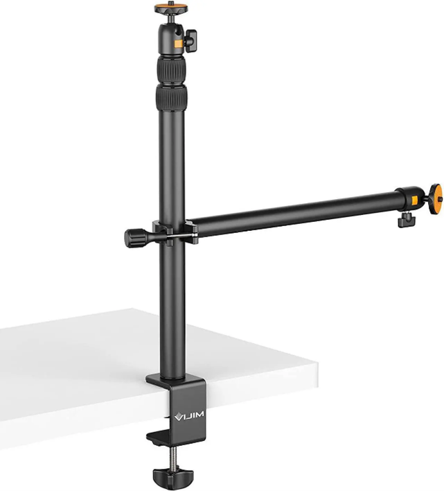
Desk mounted camera arm
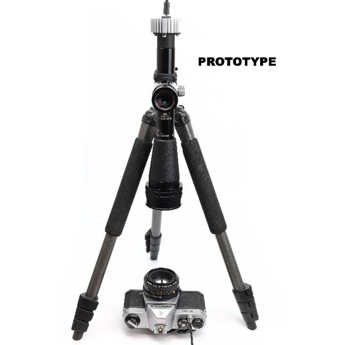
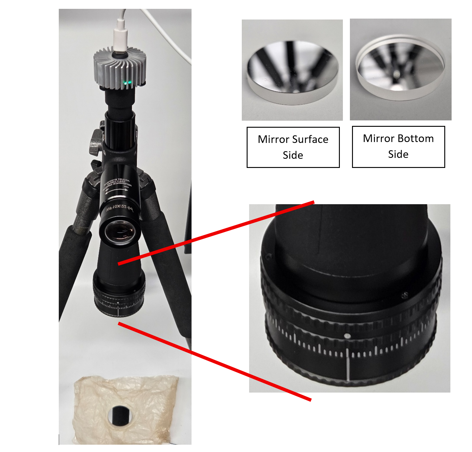
Tripod
Autocollimator Parts and Features

Principle Of Operation
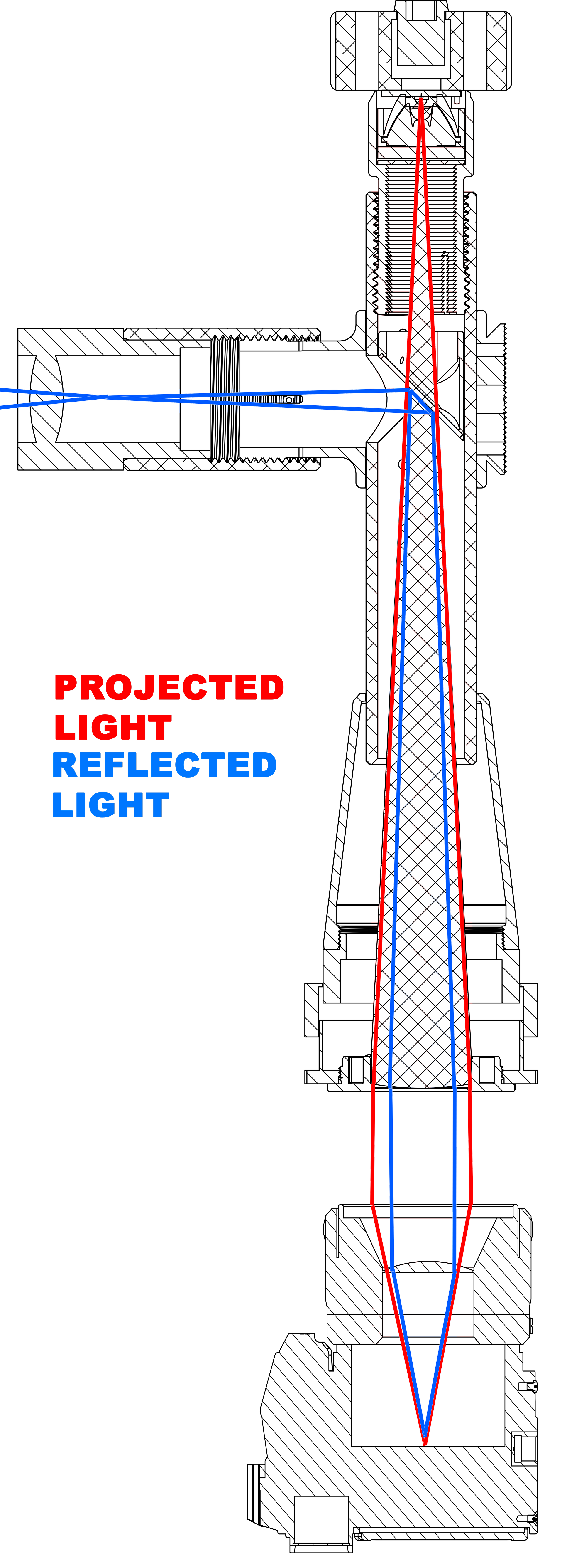
An autocollimator is the combination of a projector and a telescope. An illuminated target is projected out of the objective lens. This lens is focused to infinity, so the projected light is collimated into parallel rays.
The light then passes into a lens system and is focused, in the case of a camera, onto the film plane. Some of this light reflects off the film plane and returns to the autocollimator, where it reflects off a beamsplitting prism towards the eyepiece.
This gives the user a magnified view of the projection at the film plane, allowing for focus quality judgements to be made.
Setting Up Your Autocollimator
Step 1 – Unpack and check contents
Step 2 – Set up your mounting system
The mounting plate can interface with many Arca-Swiss style mounts, allowing you to easily attach the Autocollimator to a tripod or copy stand.
If you wish to use the ¼-20 threaded mount, there is a textured surface on the rear of the mounting plate which is intended to help prevent rotation about the screw thread. There are two optional anti-rotation set screws which can be backed out of their threaded holes using a hex key. These will help provide more grip to prevent rotation. The Arca-Swiss mount is naturally anti-rotation and self-aligning, making it the ideal choice if available.
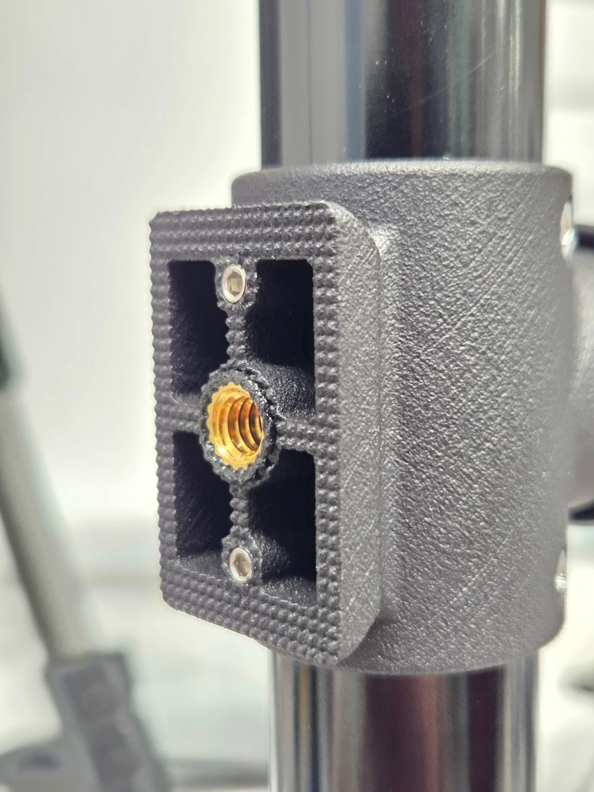
Mounting plate with Arca-Swiss features, 1/4-20 threaded insert, and anti-rotation texture and set screws
Step 3 – Attach Eyepiece
Install the eyepiece into the eyepiece barrel and secure it using the provided set screw and 1.5mm hex key.
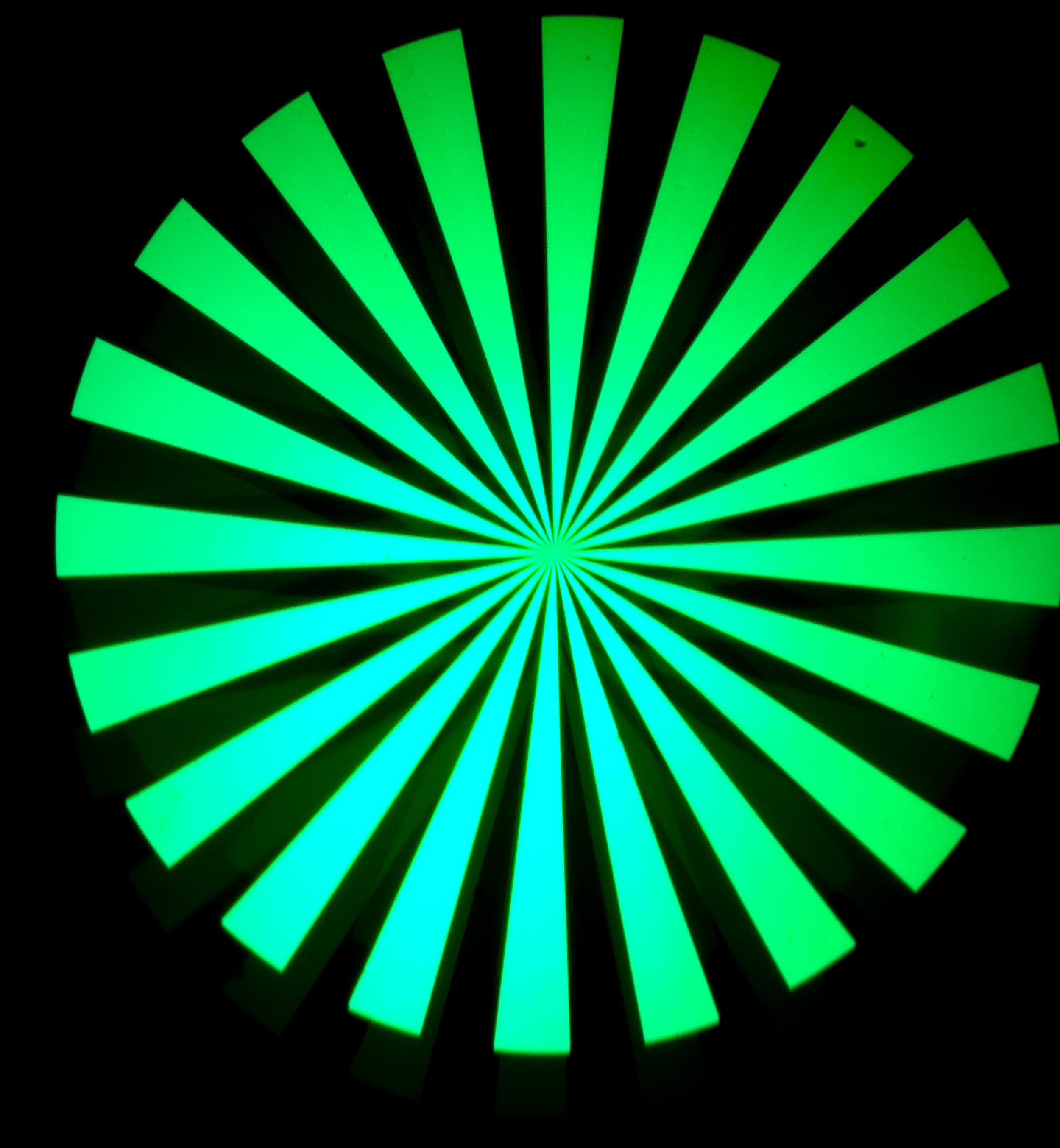
Understanding the Siemens Star Target
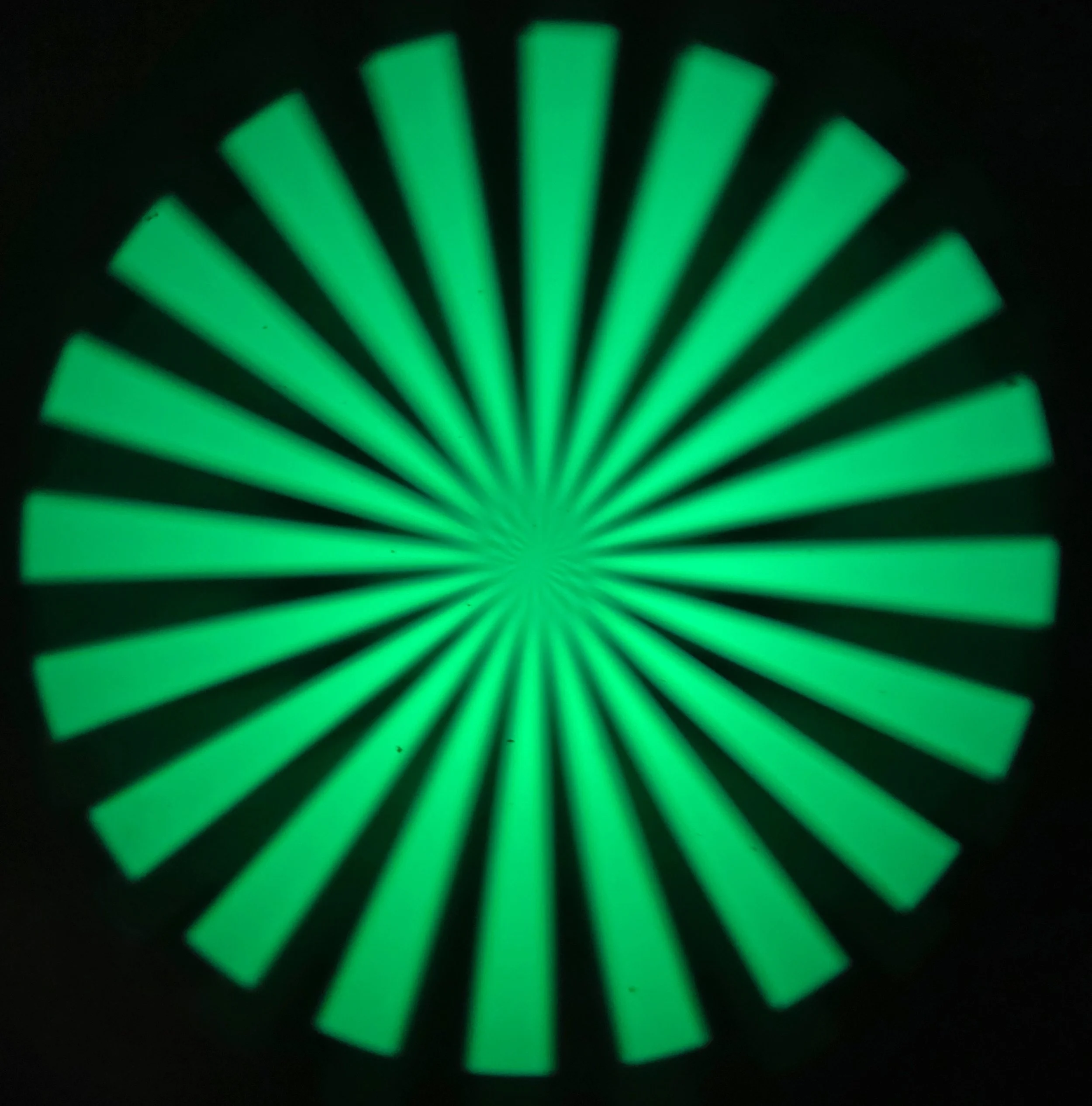
The siemens star target provides an indicator of the quality of focus by the way that the converging wedge “spokes” blur as they become thinner and thinner. The target is made from a metalized coating on glass, manufactured to a very fine resolution. The width of the spokes at the centre of the star are on the order of 1 micrometre.
If the objective lens is out of focus, or the lens being tested is out of focus or out of position, the target will be blurry, with the central spokes losing detail first, and the blurry area increasing in size proportionate to the focus error.
Since the target and objective are calibrated to appear sharp when the objective is placed at infinity (indicated by the zero mark), any blur appearing when testing a lens also set for infinity is the fault of that lens system.
The Autocollimator calibration can be checked against a high quality first-surface mirror with good flatness. The reference provided is built to wavelength / 10 flatness, before silvering.
More information is available on Wikipedia: https://en.wikipedia.org/wiki/Siemens_star

Calibrating the eyepiece to your eye
Connect the LED to a power source via the USB-C cable and USB dimmer. Turn the LED on by rotating the dimmer knob clockwise.
Place the reference mirror below the Autocollimator’s objective lens. Make sure the mirrored surface side is facing toward the Autocollimator. The distance is not important, but further distance reduces the apparent brightness of the target.
Set the objective focus to the zero mark like shown below:
4. Adjust the Autocollimator or mirror angle and position until the target appears visible through the eyepiece.
5. Rotate the eyepiece barrel until the centre of the siemens star target becomes as sharp as possible:
Note: there is a dimmer secondary reflection of the star that appears above or below the brighter one. This is normal and is more prominent when the LED light is turned up very high and the mirror is in use. Using the included USB dimmer you can darken the LED to reduce the presence of the secondary reflection without hurting the visibility of the primary. When viewing the target on film, enough light is lost that the secondary reflection is close to invisible even at maximum LED brightness.

Target out of focus
6. Double-check the objective lens is still at the zero mark and hasn’t been bumped out of place.
7. Lock the eyepiece focus by tightening the eyepiece focus lock screw using the 1.5mm hex key.
8. IMPORTANT WARNING: Do not adjust the eyepiece or reticle position using anything other than the reference mirror or an equivalent quality first-surface mirror. Miscalibration of the Autocollimator will transfer the error into any camera or lens you adjust while using it.
Target in focus
Checking the Autocollimator Calibration
The Autocollimator calibration can be checked at any time using the reference mirror.
Set the Autocollimator focus barrel at the zero mark
Place the mirror below the objective lens
Observe the target centre sharpness
Adjust the focus barrel until maximum centre sharpness is achieved.
If the maximum sharpness was not achieved at the zero mark position, adjust the eyepiece barrel until maximum sharpness is achieved at the zero mark.
Testing A Camera Lens
There are three options for what to view the target projection on:
Undeveloped camera film
First-surface mirror
Testing with film gives the best representation of the real-world performance, as the pressure plate and film flatness are taken into account. Testing with a mirror placed against the film rails eliminates any influence of the film and pressure plate on the position.
Using film
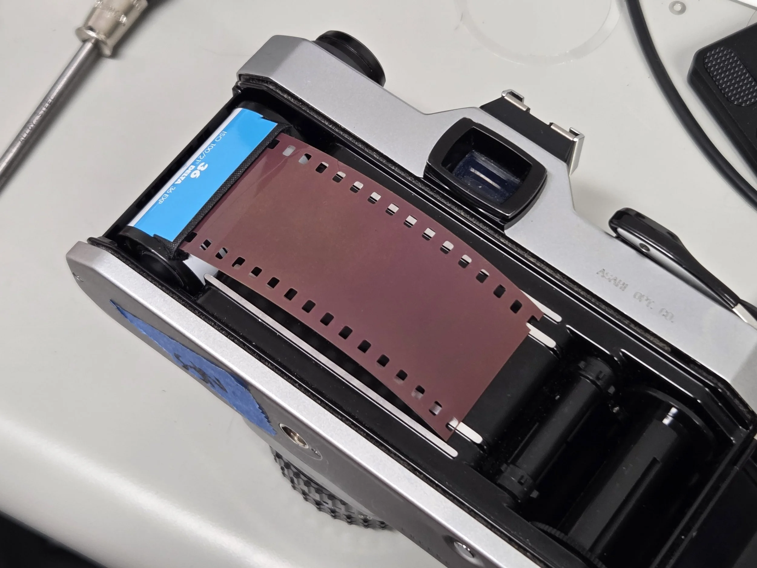
Place film emulsion-side towards the lens as you would normally load a camera.
Sticking the end of film strip in an empty film canister helps it keep in position when closing the camera back. Make sure the strip doesn’t engage with the sprocket wheel so you can cock the shutter as many times as needed.
Using the reference mirror
The provided reference mirror is 34mm in diameter, so that it can be placed across the film rails. This provides a sharp and bright image. However, using a piece of film and closing the back of the camera so that the pressure plate can act upon the film ensures that the “true” position of the film plane is being observed.
Attaching the mirror with tape helps keep it aligned when flipping the camera over.
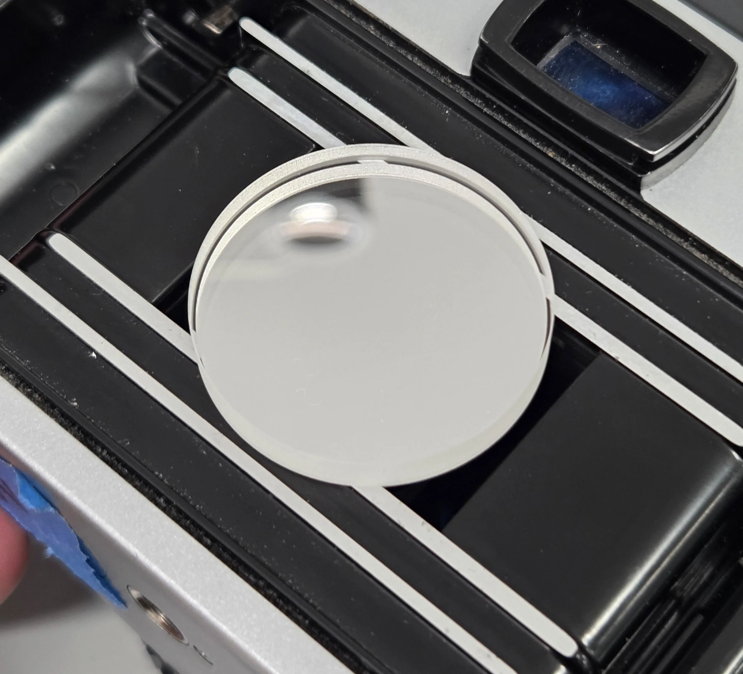
Mirror resting on the inner film rails
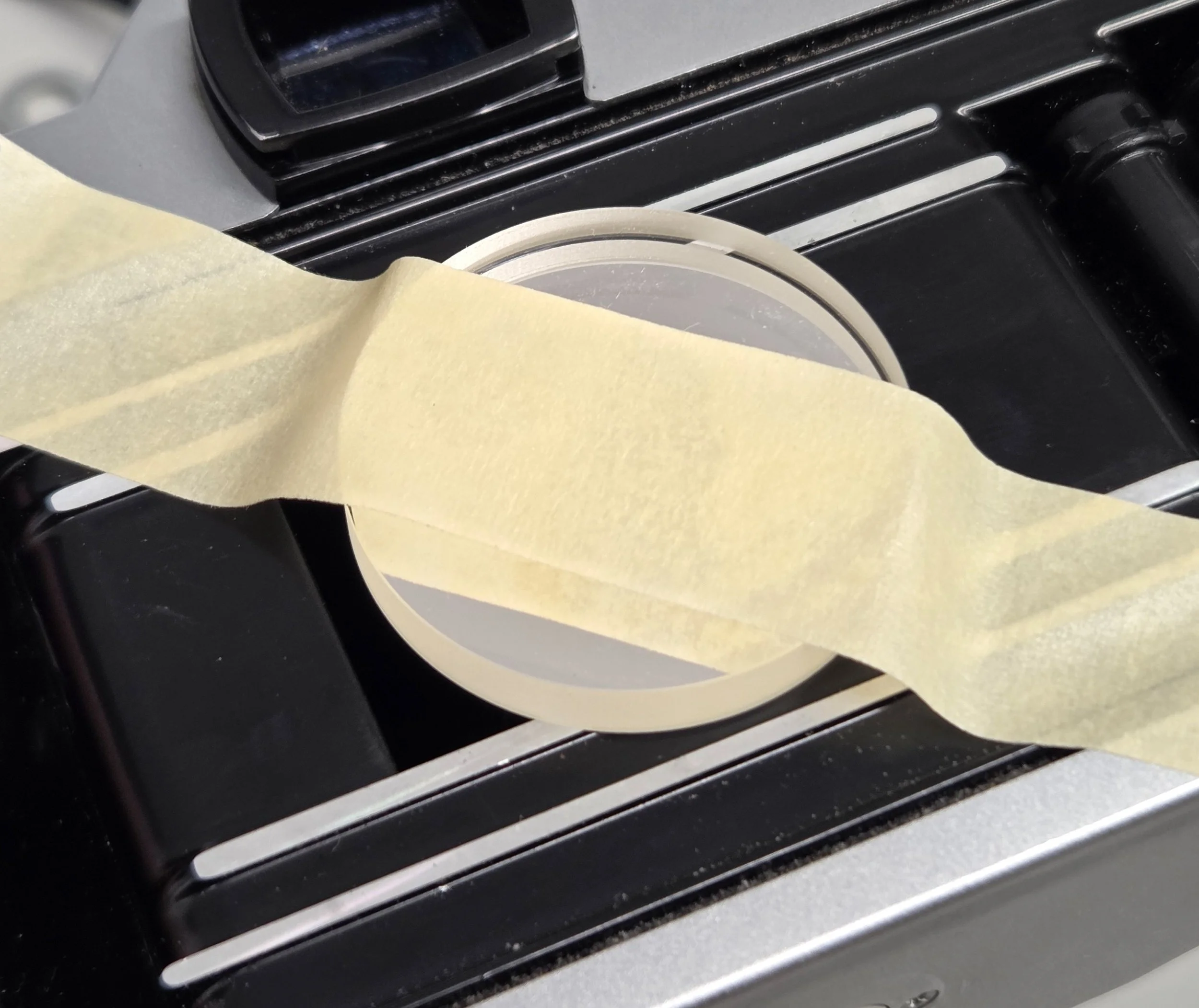
Temporarily held with tape
Checking the lens infinity focus
Initially, the camera focus should be set at infinity, and Autocollimator should be set at the zero mark. The Autocollimator objective focus is then adjusted to reach the sharpest target image possible. The amount of focus error in the camera under test is shown by the markings on the Autocollimator focus barrel.
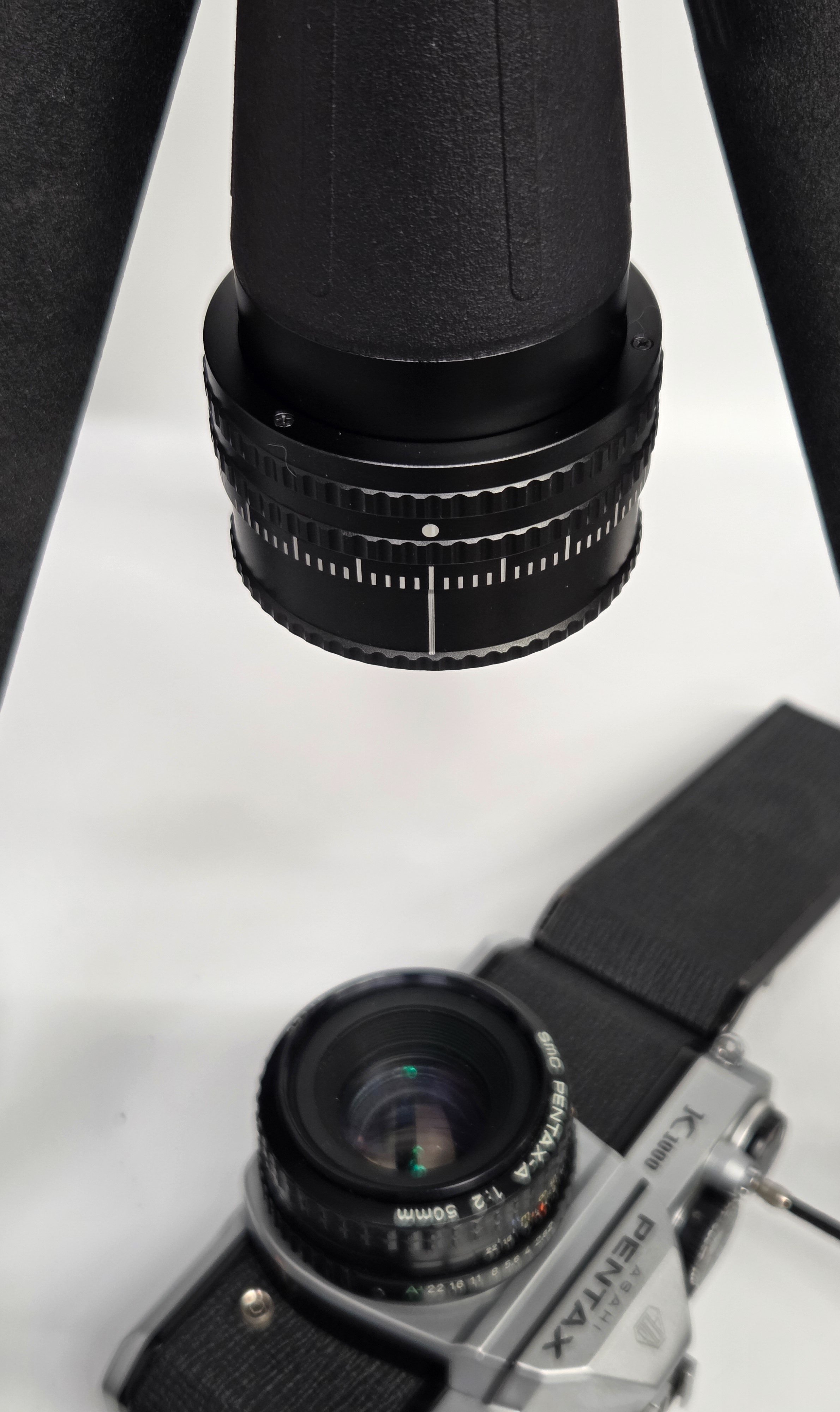
Autocollimator at zero
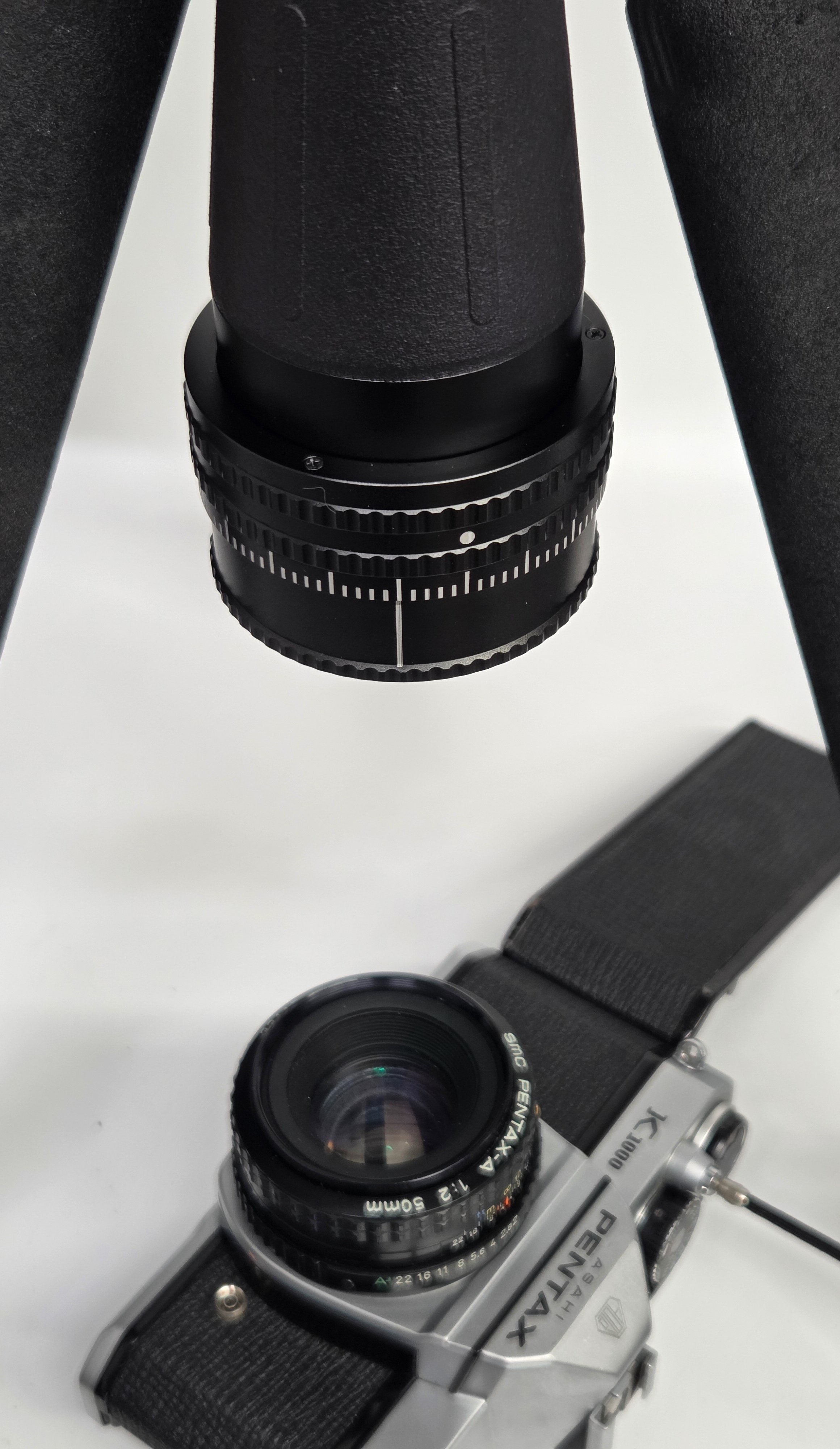
Autocollimator adjusted for sharpest image
The lens or camera can now be adjusted until the infinity focus position of the camera lens gives the best image when the Autocollimator is at the zero mark.
Target Projection on Mirror Vs. Target Projection on Film
Mirrors provide a brighter, clearer image, but film better represents where the true “real world” position of the focal plane needs to be. The mylar test strip provides a brighter image while retaining the benefits of testing with real film.
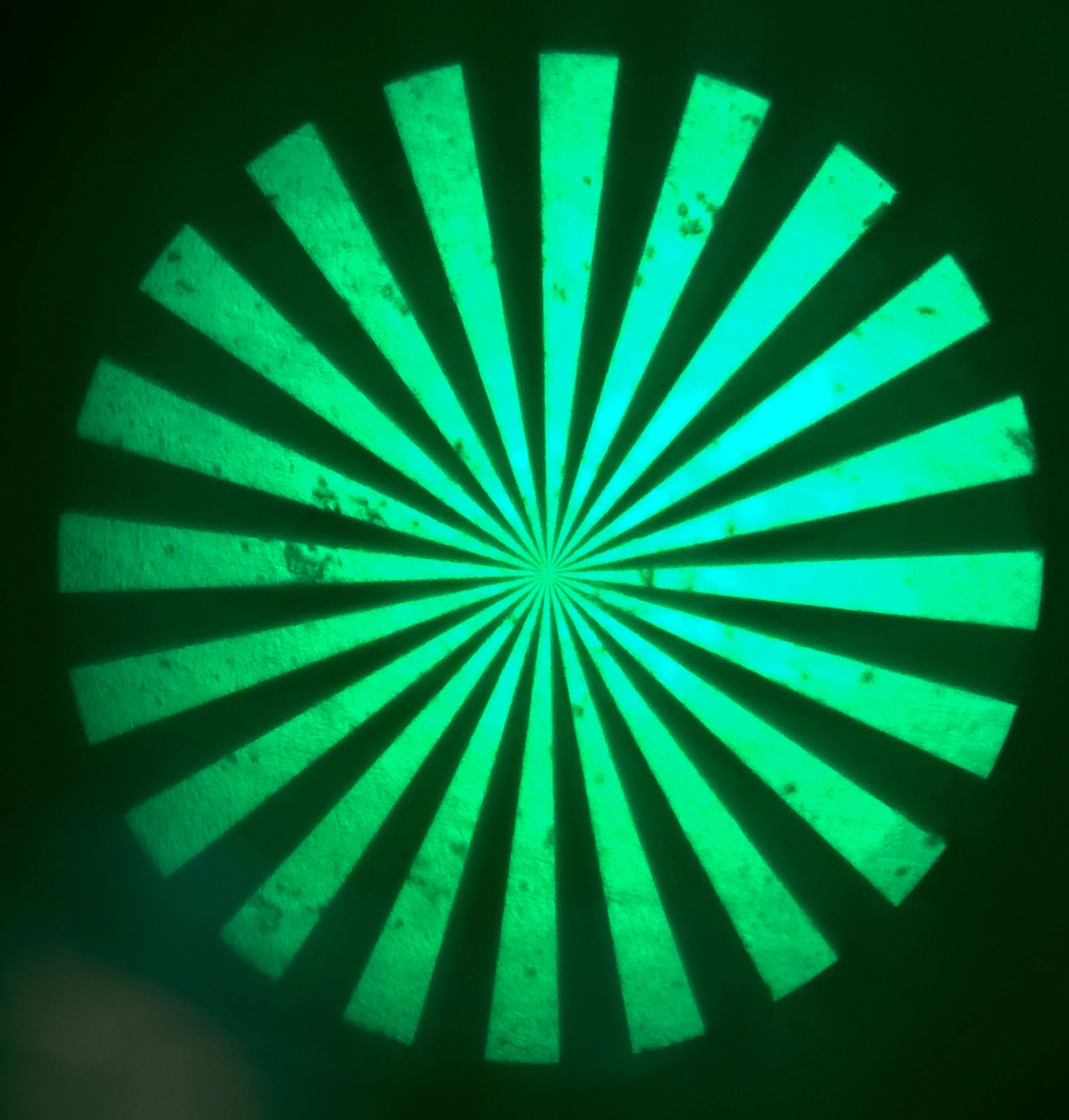
Target projection on film - note how film surface defects and dirt are visible
Target projection on mirror