
Reveni Labs Camera Tester
User Manual
Version 14 - for Firmware V1.14 - subject to change with future updates
Date: 2025-04-23

Assembly
Remove all the items from the box
Unwrap the Camera Tester, 200mm rod bundle, wall adapter and bag of parts
Peel off screen protector sheet
Find the two M5x12mm set screws in the bag of parts
Install the 200mm rods into the Camera Tester, aligning the flats on the rods with where the set screws will meet it
If you want to use it, complete the bends on the glare guard and attach it to the set screws with two M5 nuts
Attach the 100mm rods to the moving rod mount, aligning the rod flats towards the set screws
Put the moving rod mount on the 200mm rods
Plug in the sensor head and put it on the vertical rods
Plug in the 12V wall adapter and connect it to the Camera Tester (ONLY USE THE INCLUDED WALL ADAPTER!)


Assembled Unit

Setup
The Reveni Labs Camera Tester can be set up in several ways depending on the user’s preference and the type of cameras being tested. The Camera Tester can be used in a vertical or horizontal orientation. Orientation is detected at power-up and the screen and buttons are rotated accordingly. The sensor jig can be attached or removed as needed. The sensor can be held by hand if the jig is not in use.
Various Setup Options
The Camera Tester can be configured in multiple ways as shown below, to your taste or the task at hand.
Horizontal orientation is useful for SLRs with lens removed, or cameras with lens attached.
Vertical orientation is useful for cameras which have awkward opening backs, such as TLRs. It’s also useful for testing large format lenses and bare shutters which don’t have a way to sit upright. It can also help fit cameras with odd proportions such as ones with integrated vertical grips or battery grips installed.

Horizontal, with sensor jig, and glare guard

Horizontal, no jig, with glare guard

Vertical, no jig, no glare guard

Vertical, with jig, no glare guard

Vertical, with jig, with glare guard

Flash cable connected to PC port

Flash cable and hot shoe adapter connected
Sensor Heads
There are two sensor heads available. The 35mm sensor head is standard and is included with every Camera Tester. The 35mm head is used to test all leaf shutters, 35mm focal plane curtain shutters, and can be used to test medium format focal plane shutters as well, but only in the central area covered by the 35mm frame size.
Using the 35mm sensor with larger formats is made easier using various frame adapters, which are optional.
The 6-by-X head is optional and is only used to test medium format curtains from edge to edge. It doesn’t contain the extra sensor required to test medium format leaf shutters.
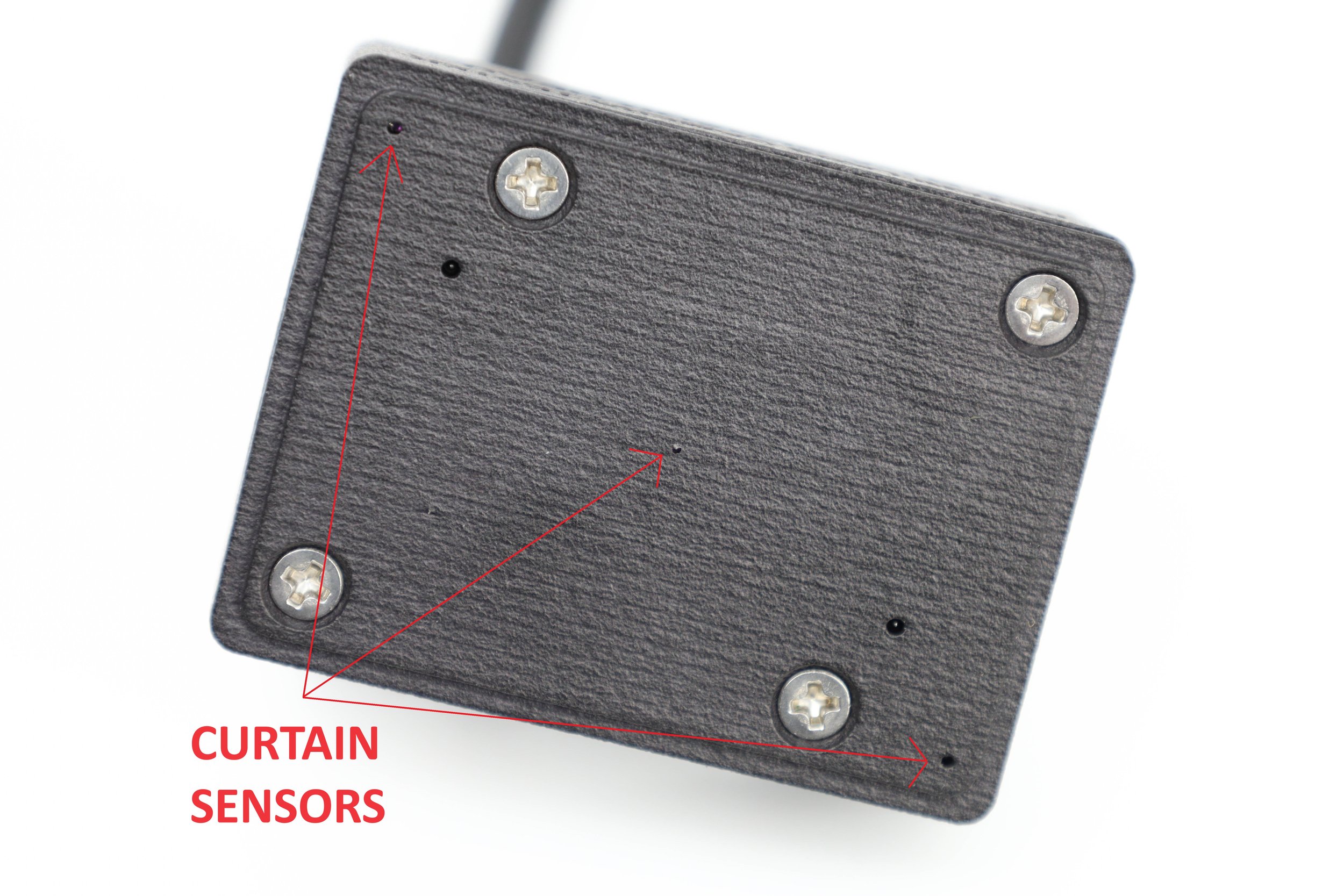
Curtain Sensors
The curtain sensors are high speed digital sensors (they only output a HIGH or LOW signal) and are used to measure the curtain travel as it crosses the film plane. These sensors only work properly when there is no lens attached to the camera, and they only work on focal plane shutters.
Analog Sensor
The analog sensor is centrally located on the 35mm head only. When light is detected, the Tester’s processor samples the light level every 20 microseconds for 1.5 seconds, totaling 75000 readings. The processor then analyzes the data to figure out the shutter opening time, wide open time, closing time, and maximum brightness. This data is also used to generate the curve display.

35mm Sensor Head

6-by-X Sensor Head

35mm Sensor Head
6-by-X Sensor Head

6X6 Frame Adapter for 35mm Sensor Head
One of several options
Sensor Head Self-Test
After the logo is displayed, a sensor shelf-test is shown. It shows a current light level for all 5 analog sensor ranges, maximum panel brightness measured during calibration, current state of all three curtain detectors, and correct function of the EEPROM memory chips.
Reflective Laser Sensor Head
A sensor head which uses three lasers to do curtain analysis on cameras with no opening back is now available. This sensor is used with the camera tester in CURTAIN SHUTTER mode, and only works on LTM (39mm thread mount) horizontal shutter cameras such as Barnack Leicas and similarly structured cameras. The data provided is the same as for CURTAIN SHUTTER mode and is therefore much more detailed and accurate compared to the simpler REFLECTIVE mode that uses the Standard Sensor head.

Reflective Laser Sensor Head

Sensor Head Self-Test Screen
Laser Head in use
User Interface
The faceplate of the device has 5 buttons, a power switch, and an LCD display. These will rotate when the device is flipped from one orientation to the other. The device checks orientation on power-up and must be powered off and back on again to change the orientation.
In this manual the buttons are referred to as UP, DOWN, LEFT, RIGHT and CENTRE.
The power button is marked by an O for off and an I for on.
Generally, CENTRE button is for entering the menu and selecting a current mode (exiting the menu).
In the menu, LEFT/RIGHT buttons change the currently selected value and UP/DOWN buttons change which value is selected. The current value is highlighted by a box perimeter.
Mode-specific button behaviour is outlined in the descriptions of the modes below.

PC Printout
The Camera Tester can sent data to a PC via USB. It does this by emulating a keyboard and works with Mac, PC or Linux. The computer’s keyboard should be set to US QWERTY layout otherwise some text characters will come through oddly.
To use PC printout:
Turn on the Reveni Labs Camera Tester without USB connected
Connect the Tester to your computer using the included USB cable
Open Microsoft Excel or another spreadsheet program
Place the cursor at cell A1 (top left corner)
Take a reading with the Camera Tester in Curtain, Leaf, Leaf Exposure or Curtain Exposure modes
Press and hold the UP button for 1 second
Some Camera Tester setting lines, extra fill-in lines like make, model, date, column headers, and first row of data will be filled in on the screen. This takes a couple of seconds to complete.
With each subsequent reading, hold the UP button again to add the new data to the spreadsheet. Don’t move the cursor from the currently selected cell, the Camera Tester will move the selected cell automatically as needed.
Exiting to the menu will reset the printout and the extra information and column headers will be reprinted again.
Testing Modes
Curtain Shutter
Curtain testing is done without a lens attached to the camera. These tests are done with the LED panel at full brightness.
Minimum shutter speed: 1/12,000 Maximum shutter speed: 30 seconds
DIRECTION: select the curtain travel direction so the distance between detectors can be correctly determined.
FORMAT: Select the appropriate frame size so that the curtain travel time can be correctly calculated.
SAMPLE: select from single readings, average, or continuous readings. After collecting averages, an average/high/low value will be displayed for each detection position.

Curtain Time Results
L/B, M, R/T: The time from when each sensor was uncovered by curtain 1 to when it was covered by curtain 2. Often there is a small discrepancy between M and L/R, due to the geometry of the camera partially shadowing the L and R detectors. M can be taken as the nominal shutter speed, and the variation between L and R highlights the variation in shutter speed from one side of the frame to the other.
C1 and C2: total travel time by curtain 1 and curtain 2, respectively. Curtain travel time is corrected for the width of the format, not the distance between detectors.
35mm: 36mm wide, 24mm tall 6x4.5, 6x6: 60mm wide 6x7: 70mm wide 6x8: 80mm wide 6x9: 90mm wide
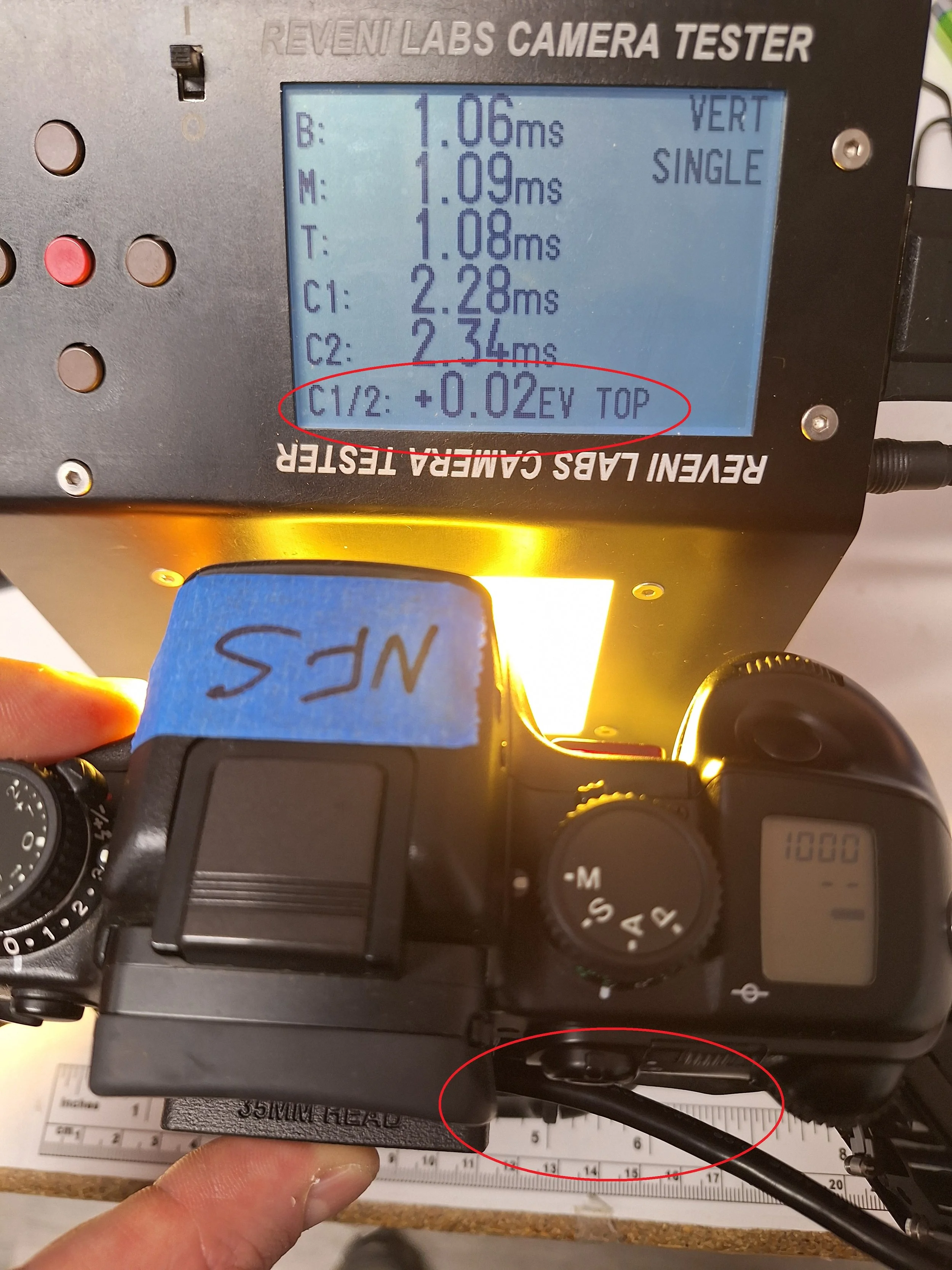
C1/2: The exposure difference from one side of the frame to the other. In the example shown, the two curtains are well synchronized.
Top right corner: Indicating the currently selected shutter direction and sample mode.
Curtain Shutter Menu Page

Curtain Shutter Time Results
Fractional Speed Results
Pressing the LEFT or RIGHT buttons will change the view to a simpler fractional shutter speed view, showing the fractional speeds instead of millisecond speeds.
Exposure variation between left and right is shown in EV.
FPS (frames per second) is printed to test the firing speed of self-winding cameras when CONTINUOUS sample mode is selected.
This screen also shows the flash contact delay following the full opening of the first curtain. Flash contact testing requires the PC port or hot shoe to be connected to the Camera Tester via the appropriate cable.

Curtain Shutter Fractional Speeds
Middle Time and Left/Right Relative Exposure Error
Pressing the LEFT or RIGHT buttons again will change to a middle time view with the left and right times replaced with the relative EV error with respect to the middle time

Curtain Shutter Middle Time and Left/Right EV variation
Curtain Times and Velocities
Pressing the LEFT or RIGHT buttons again will change to a view which depicts the front of the sensor head, with left on the left and right on the right.
The three dots shown at the corners and lower middle of the box on the screen represent the curtain detectors. The times are shown in milliseconds with the first detector triggered as t = 0.00.
The velocities of the curtains are displayed in the top left quadrant, in mm/ms (also equal to m/s). The arrow indicates the curtain direction. In the first picture shown, the red box contains the opening and closing velocities for the top half of the curtain. The blue box contains the opening and closing velocities for the bottom half of the curtain.
In the second picture, the yellow box contains the opening and closing velocities for the left side of the shutter. The green box contains the opening and closing velocities for the right side.
The third picture shows the detector positions and the corresponding dots on the screen.


Curtain times and velocities
Positions of the detectors in the sensor head relative to the dots on the screen
Average Mode Results
In average mode, the average, min and max for each sensor will be displayed in milliseconds. The quantity of averages will be counted at the top. The max variation is the largest variation in exposure on one of the sensors.

Curtain Shutter Middle Time and Left/Right EV variation
Leaf Shutter
Leaf Shutter mode is used to test any in-lens shutters such as those on point-and-shoots, not-interchangeable lens cameras, fixed-lens rangefinders, and the like. These tests are done at full LED panel brightness.
Minimum shutter speed: 1/1000 Maximum shutter speed: 1 second
SAMPLE: Single or running average mode can be selected. After briefly showing the graph and results, the averages will be displayed.
The Camera Tester performs a high speed analog analysis of the shutter performance, and determines the opening time, fully open time, closing time, and effective shutter speed.
Topen: Shutter opening time (from initial detection to 95% maximum brightness)
Twide: The total time wide open (from first reading at 95% maximum brightness, to last reading at 95% maximum brightness)
Tclose: Shutter closing time (from 95% maximum brightness to 5% maximum brightness)
Teff: the effective exposure time, from the middle of the opening time to the middle of the closing time.
FRACT: fractional time for reference
Note: The opening/closing time will be longest at the widest aperture, and will be shorter at smaller apertures, as the time it takes for the shutter to uncover the smaller aperture is less than it takes to open completely. This will be reflected in the results you see. The effective shutter speed should remain similar at all apertures.
IMPORTANT INFORMATION BELOW!
RANGE: This is additional data regarding the Tester’s operation. the percentage displayed is how much of the sensor’s detection range was used (100% means that brighter light cannot be measured). If the number is too low, the Tester will struggle to get a quality reading of open and closing times, or may not detect the shutter at all.
SENS: The sensitivity level is shown from 5 (most sensitive) to 1 (least sensitive). Pressing the RIGHT or LEFT buttons will adjust the sensitivity down or up. Sensitivity should be set to balance the reading between 100% of max and 5% of max (or if too low, not detecting at all).
Most cameras or large format lenses being tested at wide open aperture need a sensitivity setting of 1 or 2.
Graphic Curve
After displaying the results, the exposure curve is displayed. This is based on the raw data that the numerical results were calculated from. This is to help ensure a good reading was taken because the exposure curve will appear irregular if the sensor was misaligned or there is a major mechanical issue with the shutter.
Press the DOWN button to view the curve again.

Leaf Shutter Menu

Leaf Shutter Results

Leaf Shutter Exposure Curve
Leaf Exposure
This mode will permit testing of auto-exposure cameras which use a leaf shutter. It will measure both the brightness at the film plane (to determine aperture) and measure shutter speed to determine the correct exposure and whether the camera achieved this.
Minimum shutter speed: 1/1000 Maximum shutter speed: 1 second
These tests must be done with a lens attached, with the sensor placed at the camera’s film plane.
When on the results page, press the RIGHT/LEFT buttons to change the sensitivity, and the UP/DOWN buttons to increase/decrease the panel brightness.
Sensor sensitivity must be adjusted to ensure the sensor is triggered, but isn’t saturated to maximum measurable brightness during the exposure. Adjusting the sensitivity so the % OF MAX is not at 100% is important. LED panel brightness can be adjusted along with the camera’s meter K factor.
R: The sensor head range is displayed at the bottom. This helps the user make sure they haven’t set the aperture too low and the readings are not utilizing much of the sensor head’s available capacity, reducing accuracy. If the sensitivity is set to a low value (say 1) and the lens is set to a narrow value (say f16) the shutter fire won’t be detected.

Leaf Exposure Menu

Leaf Exposure results
Curtain Exposure
This mode will operate similarly to the leaf exposure mode, except making some alterations to compensate for the curtain travelling past the sensor instead of the centrally-opening leaf shutter.
Minimum shutter speed: 1/1000 Maximum shutter speed: 1 second
These tests must be done with a lens attached, with the sensor placed at the camera’s film plane.
This mode will only test the shutter speed in the centre of the curtain travel, and provide only one shutter speed result. Proper full curtain checking should be done in Curtain Shutter mode with the lens removed. This mode’s primary function is checking the exposure system and automatic lens stop-down.
When on the results page, press the RIGHT/LEFT buttons to change the sensitivity, and the UP/DOWN buttons to increase/decrease the panel brightness.

Curtain Exposure results

Typical curtain exposure curve
Reflective Shutter Test
This mode allows for testing shutters which do not have through-body access for the sensor head to sit at the film gate.
Minimum shutter speed: 1/1000 Maximum shutter speed: 1 second
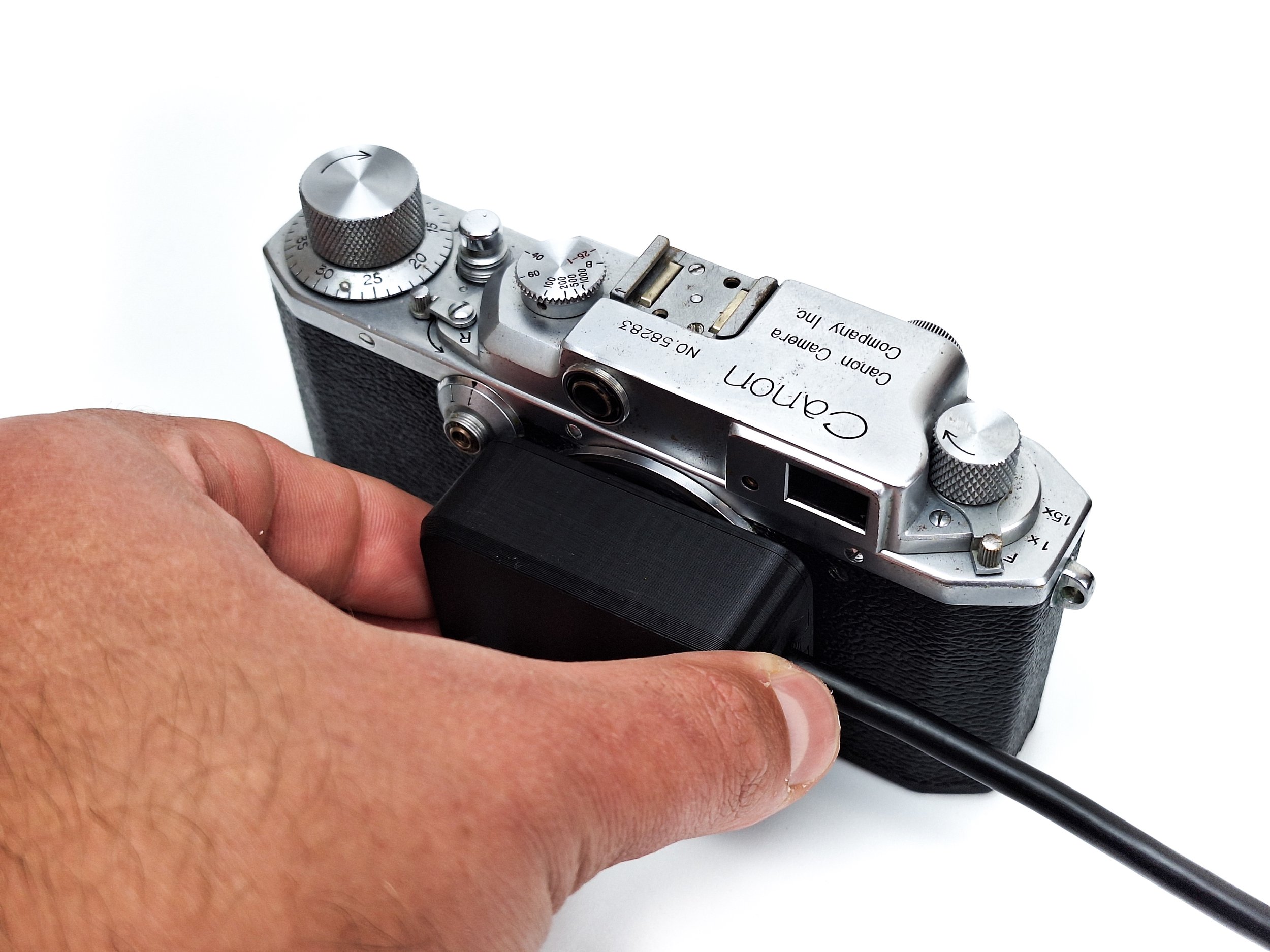
The mirrored card included with the Camera Tester is placed at the film gate by inserting into the camera in place of film. The sensor head is aimed into the lens mount and the shutter is fired. The reflection of the red LED light on the sensor head is detected and timed.
Some lateral movement can be applied to test the shutter in different sections.
This mode is only to be used on cameras which don’t have through-body access for normal curtain testing because it doesn’t provide as much information and is not as accurate.

Sensor head in place during reflective test

Reflective Menu - shows use instructions

Reflective measurement result
Light Meter
This mode sets the light panel to the selected reflected EV equivalent, so that reflective meters (both handheld and in-camera) can be tested against it. The LED panel should fill the field of view of the light meter, so when testing non-TTL camera meters, be sure to place the metering cell as close to the panel as possible.
Incident meters can be tested by placing the incident dome against the panel when taking a reading. Incident meters should read ~2.5 EV less than the stated panel EV value. The expected reading for an incident meter is calculated and shown on the screen.
Lux can be calculated from EV with this formula: Lux = 2.5 * (2^EV)
EV can be calculated from lux with this formula: Ev = (log(Lux) – log 2.5) / log2
The panel EV can be adjusted in the menu, and also when in light meter mode by pressing the UP and DOWN buttons.

Light Meter Menu

Light Meter screen
Aperture Test
This mode permits testing of apertures. The lens must be camera-mounted or otherwise placed so that the sensor is located at the film plane for infinity focus. The shutter must remain open continuously, either by a locked cable release or by holding the shutter button in bulb mode.
The measured aperture will be continuously read out on the display. The Camera Tester will automatically adjust the sensor sensitivity range as the measured brightness varies.
T: This is the measured aperture displayed as a T-stop. T-stops are like F-stops (a ratio of focal length / aperture diameter) with lens transmissibility (the actual amount of light reaching the film) included.
D: This is the Difference between two apertures. Pressing the RIGHT button will zero the reading, then the aperture can be varied to see the difference in light level, displayed in stops.
Other numbers shown are the sensor head range and raw brightness readings.

Aperture Test screen with D zeroed

Aperture Test screen with D zeroed

Aperture Test screen showing 0.99 stop difference between T5.7 and T8.0
Calibration
Calibration mode is used to calibrate the light panel using the 35mm sensor head. The Camera Tester is completely self calibrating, except for the light panel’s MAX EV, which is tested at the factory.
The factory brightness is measured and written on the label on the bottom of the Camera Tester. The maximum brightness is not expected to vary over time.
If you wish to confirm the light panel’s MAX EV, it can be re-done by the user using a reflective or spot meter which can read out in 1/10th EV or better. When the calibration mode is navigated to in the menu, the LED panel automatically switches to maximum brightness, so this is when the maximum EV can be measured. Based on the supplied maximum panel EV, the 35mm Sensor Head will make successive measurements to find the LED panel constant-current level needed to get the lower EV values.
Calibration can be confirmed using a known good reflective light meter in light meter mode, checking the brightness at each EV level matches what is expected.
Calibration Process
The 35mm Sensor Head must be placed so that it is touching the LED panel face. The room lighting should be dimmed or the glare guard should be attached, as stray light will affect the calibration of lower EV values. If needed, cover the sensor and light panel with a dark cloth to keep out external light during calibration.
Once started, the process takes a few minutes to complete.
If calibration is accidentally activated, power off the Camera Tester to stop it. The calibration values will only be over-written when the calibration process completes.


Calibration menu
35mm Sensor Head in the calibration position

Curtain detector trip level calibration

Curtain detector trip level calibration complete

Panel EV calibration starting

Calibrating Curtain Detectors
There are further manual adjustments available for fine-tuning the curtain detectors. There are two options: balance and offset.
Adjusting balance and offset should be done with a known good-working modern 35mm SLR that can comfortably perform at a high shutter speed, ideally 1/1000.
Camera Testers sold after April 4th, 2025 will come pre-calibrated and shoudln’t need adjustment.
Balance: This adds a variance between the left/bottom and right/top detectors to cancel any variation between them. The test is done by flipping the sensor 180 degrees, to differentiate camera shutter error from sensor error.
In the images to the right showing the unbalanced sensor, note how the shutter exposure error is on the bottom both times. If the error was in the camera, it would be on the bottom with the sensor one way and on the top with the sensor the other way.
1. Set up the Camera Tester to get the camera close to the light source, and in such a way that the camera won’t move much during the tests. The lens mount should be parallel to the light source and remain that way during the tests.
2. Measure the shutter with the sensor head cable coming out to the left, and again with the sensor rotated 180 degrees so the cable is coming out at the right. Note the Left/Right (or Bottom/Top) readings. Flipping the head helps reveal the sensor error that is consistent, versus shutter error which will move from one side to the other when the sensor is flipped.
For the unbalanced example shown, note how B is always 0.06-0.07 longer than T, and the C1/2 error is always at the BOTTOM. If this was shutter error, flipping the sensor would reverse the error side, as the sensor doesn’t know that it has been flipped over.
3. Enter the menu, navigate left to the calibration page, scroll down to the “BALANCE” line. Adjust the balance to match the difference between the B/L and T/R reading, where a higher B/L means that a negative balance is required. For the images above, B = 1.13 and T = 1.06, flipped B = 1.10 and T = 1.04, so an balance of -0.06 is required.
4. Navigate back up the screen to the top line, then navigate right to the curtain shutter test and perform the curtain shutter tests again. The difference between B/T and L/R should now flip when the sensor head is flipped, as this now represents the actual shutter error.
Panel EV calibration underway

Calibration Menu
Unbalanced - sensor upright
Balanced - sensor upright

Unbalanced - sensor inverted

Offset: This alters the results of the shutter reading in 0.01ms increments, up or down, to resolve any error in the 100us range at very high shutter speeds. This requires a trustworthy shutter as this adjustment will impact all curtain measurement accuracy if set incorrectly.
Using a modern, known-good 35mm SLR, test the speed at 1/1000 and then adjust the offset so that the result on the middle detector is 1.00ms. Then test the shutter at the highest speed, ideally 1/4000 or higher, and check that the reading is within 0.01ms or so of the expected value, and that all three detectors trigger.
If you don’t have a camera that you trust well enough to perform this test, leave the offset value at 0.00.
Balanced - sensor inverted
Firmware Update
The firmware updating process requires a data-capable micro USB cable and a PC or Mac.
Disconnect the 12V DC power from the Camera Tester (the position of the Camera Tester power switch is not important)
Plug the micro USB cable into the computer
Press and hold the button closest to the light panel
Connect the micro USB cable from the computer into the USB port on the side of the Camera Tester
The Camera Tester will appear as a storage device called “RPI-RP2”. The backlight will come on but the Camera Tester should not start as normal or display anything on the screen. If it shows normal running behaviour, unplug and repeat steps 3-4.
Click and drag or copy and paste the firmware file (.uf2 filetype) to the storage device. Agree to any prompts about transferring the file.
The Camera Tester will automatically boot and begin running.
Unplug the micro USB cable from the Camera Tester
Connect the 12V DC power
On startup, observe the software version under the Reveni Labs logo to see it has updated successfully.

The button being held down
Service and Repairs
Please contact Reveni Labs directly if your Camera Tester has a problem and needs repair. Spare and replacement parts are available and the Camera Tester was designed with repairability in mind, so shipping it in for repair shouldn’t be necessary. Please use the Contact Us link below to get in touch.
https://www.reveni-labs.com/contact
FCC (United States only)
This device complies with Part 15 of the FCC Rules.
Operation is subject to the following two conditions:
(1) this device may not cause harmful interference, and
(2) this device must accept any interference received, including interference that may cause undesired operation
ICES(Canada only)
ICES-003
This Class B digital apparatus complies with Canadian ICES-003.
Operation is subject to the following two conditions: (1) this device may not cause harmful interference and (2) this device must accept any interference received, including interference that may cause undesired operation.
NMB-003
Cet appareil numérique de la classe B est conforme à la norme NMB-003 du Canada. L’utilisation de ce dispositif est autorisée seulement aux conditions suivantes: (1) il ne doit pas produire de brouillage et (2) l’utilisateur du dispositif doit être prêt à accepter tout brouillage radioélectrique reçu, même si ce brouillage est susceptible de compromettre le fonctionnement du dispositif.
This product is designed to meet RoHS compliance regulations.
Protect the environment by not disposing of this product with household waste (2002/96/EC).
Check your local authority for recycling advice and facilities (Europe only).
Safety Warnings
If smoke or a bad odor comes from the device, unplug it and do not use it again without contacting Reveni Labs.
Never use the Reveni Labs Camera Tester in an environment containing flammable gasses as there is a danger of explosion or fire.
Do not allow children to play with the Reveni Labs Camera TEster as it and its parts are small enough to present a choking hazard.
Keep out of reach of children or pets.
Do not open the Reveni Labs Camera Tester unless instructed by Reveni Labs.


Contact
Email matt@reveni-labs.com or use the Contact Us page to report any bugs, make suggestions, or ask questions.